#pathtozerocarbon, #sustainability
14 – MEP, Refrigerants, Equipment + Carbon
We know a lot about the energy use carbon profile of buildings from Post 6 and Post 13; our understanding of the emissions to construct maintain, and replace the systems that heat, cool, illuminate, and power our buildings is in its infancy. Nearly all so-called ‘whole building’ LCAs omit emissions from the material used for air handling units, ductwork and piping, terminals, electrical systems, and the impacts of refrigerants. While we don’t yet have widespread data, MEP (Mechanical, Electrical, and Plumbing; A1-A3, excluding refrigerants) systems may contribute roughly 10-25% of a new building’s embodied carbon, and could be 50% or more of the embodied carbon on a renovation.
Load reduction (energy efficiency) and electrification are still the primary low-carbon strategy for MEP systems; doing these with low-carbon refrigerants impact is even better. Soon we will also be able to refine decisions based on comparing the total embodied carbon of MEP systems as well as their resilience and longevity. However, no expansive studies comparing mechanical system types to one another have been completed, largely due to the complexity and the number of components in these systems and lack of Environmental Product Declarations (EPDs).
Instead, some available resources to help make directional decisions include:
- CLF MEP study (2019), is a comprehensive study, including a cursory MEP LCA calculator.
- Boston Society of Architects (via AIAU) offers an online video on MEP embodied carbon (2020) as part of a 10-part series.
- Intro video and quarterly forum recordings from the MEP 2040, an industry organization working on energy use, embodied carbon, and refrigerant use of MEP systems.
- Greater London Authority set building benchmarks estimating MEP/Services embodied carbon at 21% of the total.
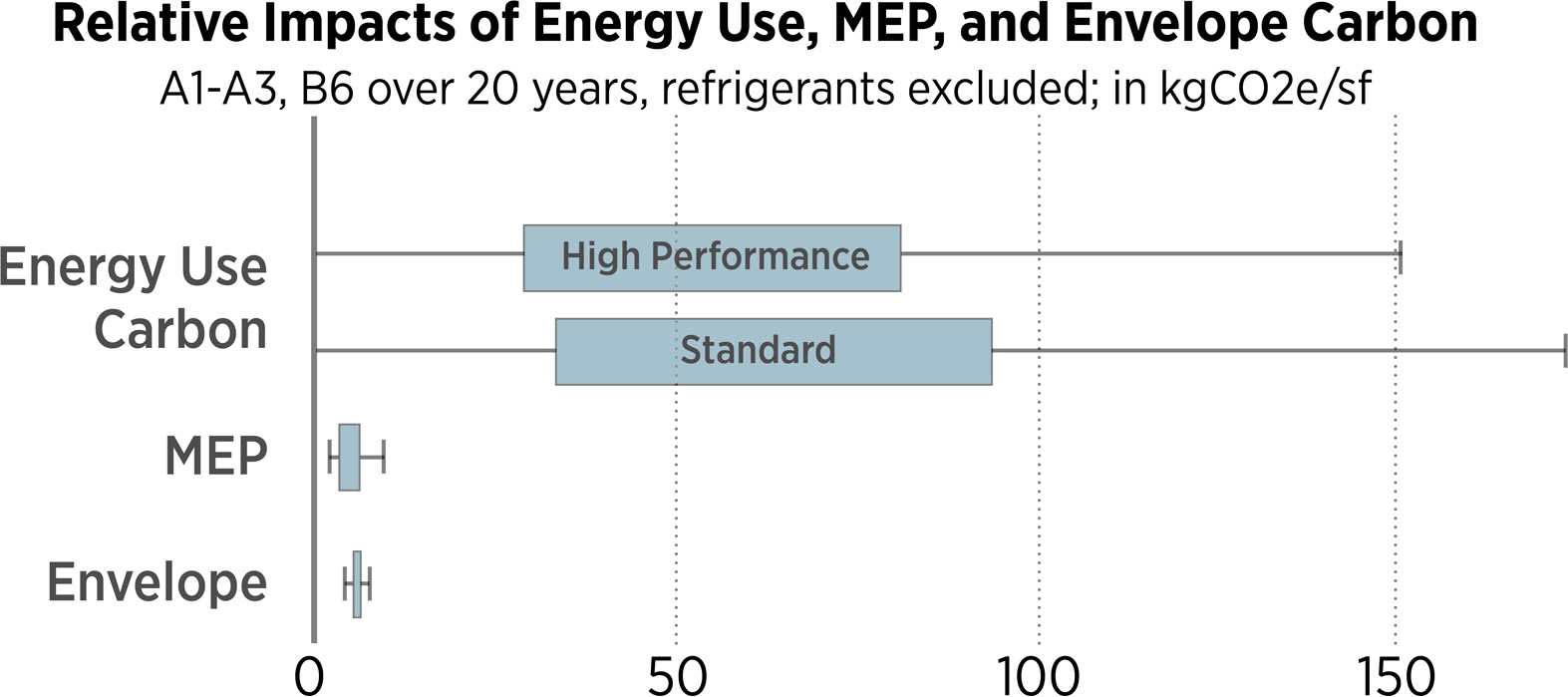
Emissions from energy use are the biggest impact and opportunity for most buildings today in the US compared to embodied carbon of envelope and MEP systems. These projections use the CLF MEP study data for MEP embodied carbon ranges, energy use based on the buildings used in the CLF MEP study with NREL Cambium mid-case energy use CO2e projections for the next 20 years, and envelope embodied carbon ranges from Kaleidoscope, normalizing to building area. Refrigerants, fire protection systems, and technology embodied carbon are not included.
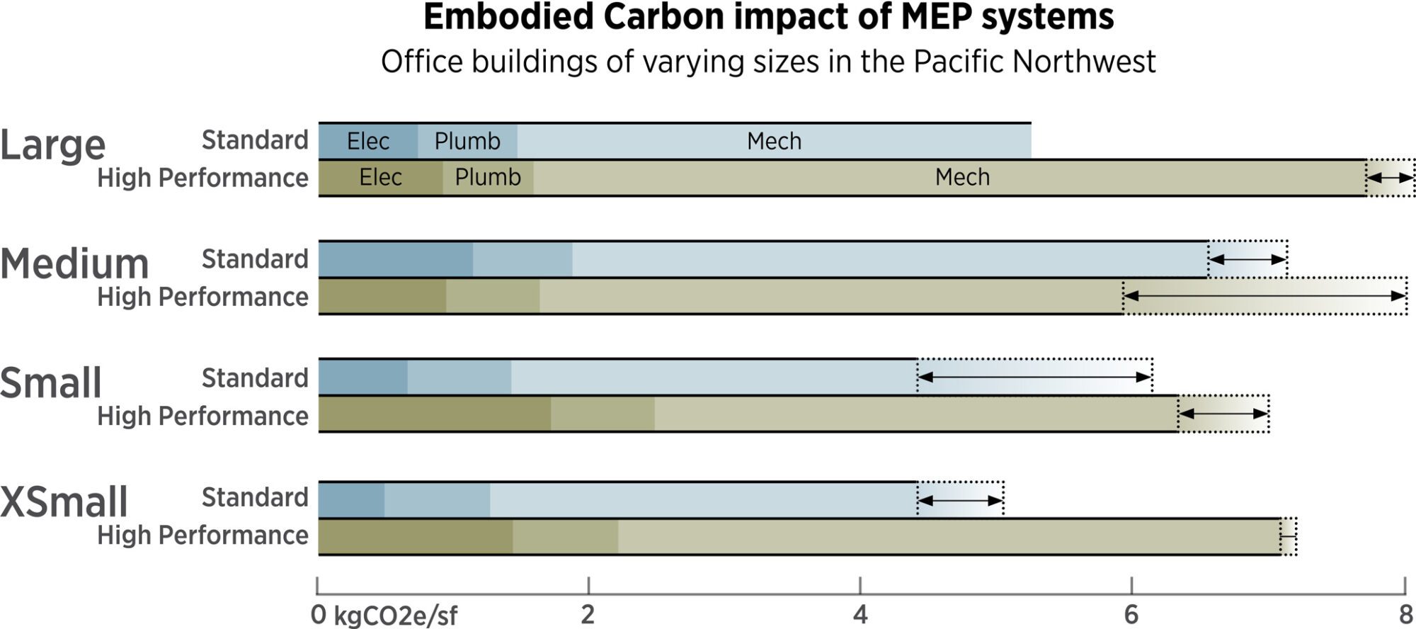
The CLF MEP Study provides an early glimpse of the total embodied carbon from MEP systems for office buildings of different sizes. While this is the best study available, it uses very limited data, excludes many electrical components, excludes energy generation, and only includes A1-A3.
MEP 2040 Commitment
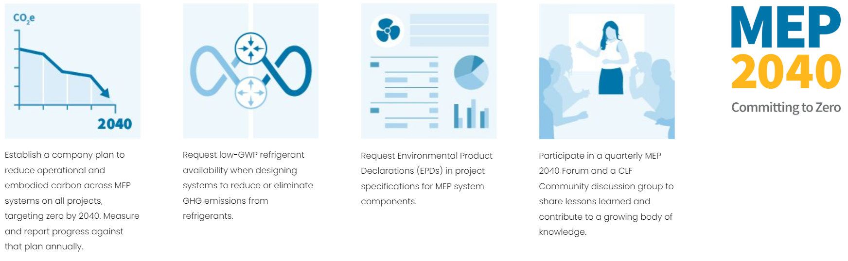
Similar to the emergence of the Architecture 2030 Challenge and the SE 2050, the MEP 2040 Commitment developed out of a need for community engagement on MEP carbon issues. MEP 2040 targets net zero operational carbon by 2030 and net zero MEP embodied carbon by 2040. Signatories commit to developing a company plan to address these emissions, requesting low-GWP refrigerants and EPDs for equipment, and participation in MEP 2040 forums. Resources include several guides, quarterly forums, working groups, and templates and guidance for engaging clients and manufacturers.
Based on the few studies completed, it appears that nearly any investments of embodied carbon in MEP systems that significantly reduce operational energy use carbon through efficiency and grid-responsiveness are worthwhile. Refrigerants are the major exception and need to be addressed today: we have good data on their contribution to global warming and options exist. Specifically, Variable Refrigerant Flow (VRF) systems often use large refrigerant quantities and site-connected piping that is more prone to leakage; while this system is more efficient than some others, refrigerant leakage can offset that efficiency.
This post will focus primarily on mechanical systems (and the plumbing systems that support them) for three reasons. 1) they are responsible for most of the embodied carbon among MEP systems and 2) system choice is a major decision point since operational energy use by mechanical systems is the primary carbon emissions source in most buildings today and 3) refrigerant leakage emissions are determined, in part, by mechanical system choice.
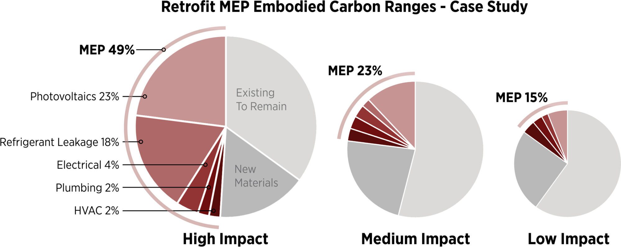
The LETI Embodied Carbon Primer includes three ranges for an existing office retrofit showing the embodied carbon of MEP systems relative to other embodied carbon emissions. Note that embodied carbon from renewable energy photovoltaics is nearly equal to the combined sum of all other MEP system embodied carbon (though PV embodied carbon has been decreasing rapidly), meaning that reducing energy use is a primary embodied carbon reduction strategy in addition to being the primary operational carbon reduction strategy; note also that refrigerant leakage is the largest variation between schemes.
MEP Basics and Comfort
Much of what we expect from modern buildings relies on Mechanical, Electrical, and Plumbing (MEP) systems. We expect mechanical systems to keep us thermally comfortable and provide fresh air and vent indoor pollutants with minimal energy inputs. We expect Plumbing systems to convey clean water, remove effluent, provide building stormwater drainage, and support mechanical systems with hydronics and boilers. Lighting systems provide interior and exterior illumination with controls for daylighting, occupancy, and scenes. Electrical power systems transform electricity from the grid to power all building plus electrical vehicles. Some buildings also have emergency power generation and are increasingly including on-site renewable electricity generated from photovoltaics.
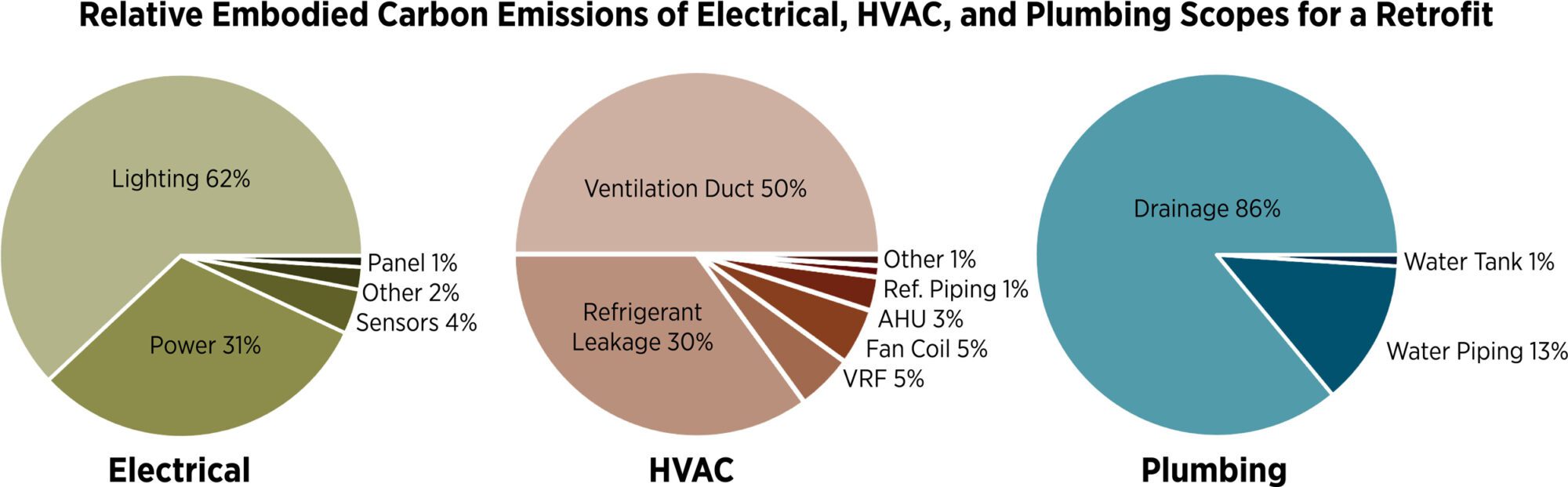
The LETI Embodied Carbon Primer includes 3 retrofit scenarios from Elementa/Introba illustrating relative embodied carbon emissions from subsystems within Mechanical, Plumbing, and Electrical disciplines. It excludes renewable energy and includes scope specific to this one retrofit project.
Human thermal comfort doesn’t have its own post but is critical to understanding why HVAC systems use energy. Providing human thermal comfort starts with a great envelope, which reduces both energy use carbon and the embodied carbon of MEP systems used to keep people comfortable. In many buildings, especially those with too much glass, too little insulation, or too much air leakage, people are uncomfortable near the perimeter. Complaints from these occupants leads to facility managers adjusting the set points – thermostat temperatures that turn on heating or cooling systems – which can radically increase energy use. Modified set points and thermal comfort near building exteriors is not often addressed during design. With high performance envelope design, entire mechanical systems can be eliminated, reducing energy use and embodied carbon. Ceiling fans, radiant systems, and task/ambient space conditioning can provide more comfort with less energy input.
Despite not having much data on the embodied carbon of mechanical systems, we know that great massing and envelope design – with a reasonable window to wall ratio paramount – will increases comfort and reduce the embodied carbon of a mechanical system by reducing peak loads and total amount of equipment required (Post 12). This also reduces the total energy generation required, which has a very large effect on total embodied carbon when energy generation and storage systems are included.
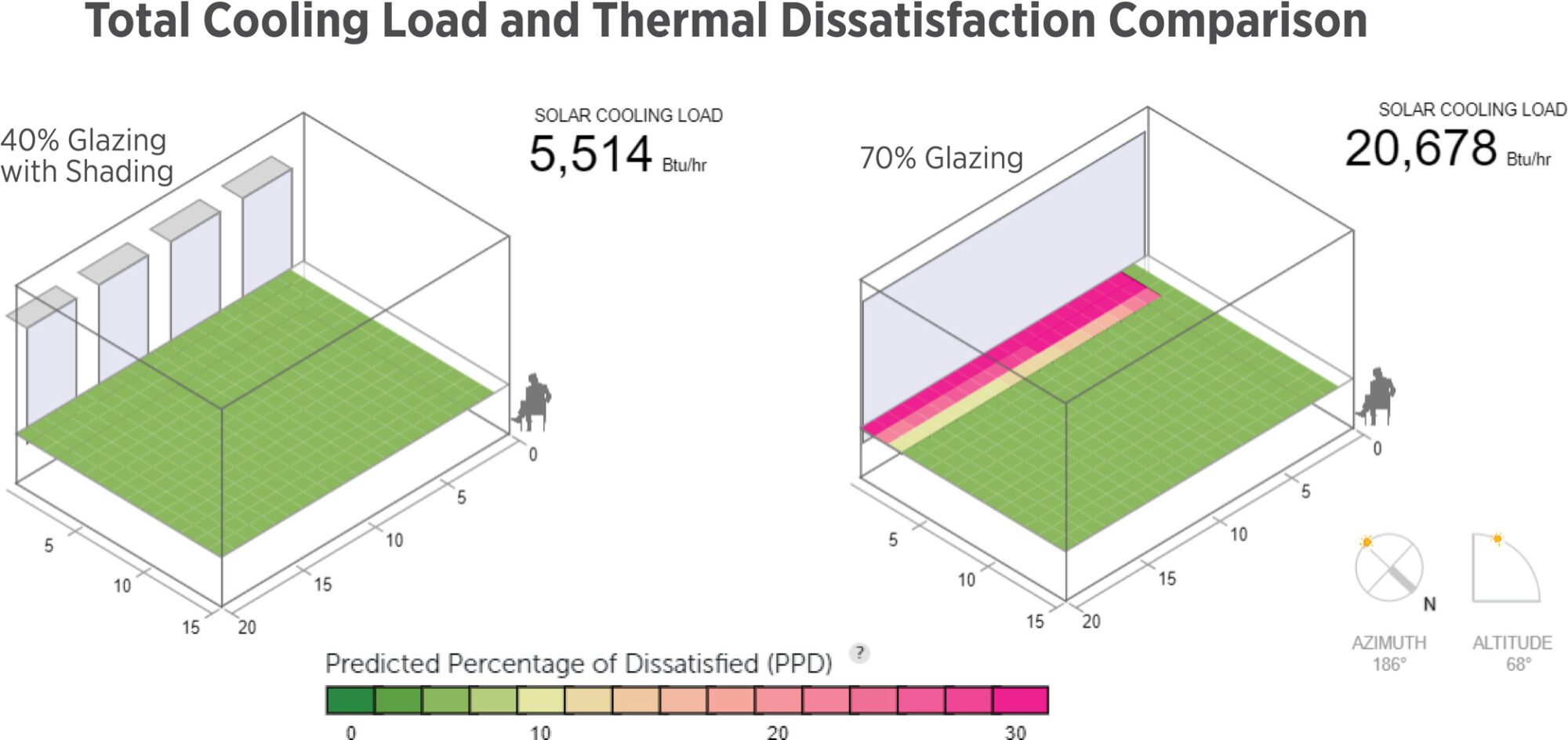
Two identical spaces are compared for thermal dissatisfaction and total cooling load over one summer hour using the Solar Comfort Tool. On the left, 40% glazed wall with 18” overhangs. On the right, 70% glazed wall. The space on the right has nearly 4x the solar cooling load (if this is a peak time it will increase embodied carbon and refrigerant use), and even with that additional cost, carbon, and mechanical size, the area 3-5’ from the perimeter is extremely uncomfortable. People in this area often complain, resulting in increased cooling, which significantly increases energy use and peak electricity demand, and creates thermal comfort problems for those not near the perimeter.
Many mechanical systems are oversized in residential and commercial buildings, causing issues such as energy waste, discomfort, moisture issues, and more. Oversizing leads to higher embodied carbon and refrigerant use and most equipment also runs at suboptimum efficiency when oversized.
Some oversizing can be justified when future weather and effects of climate change are considered; more heat waves, higher humidity, or other changes that may be hyper-local. Many climate data files used to size building systems today are from 1976-2005 (TMY3) and do not include the past nine years even though they are the hottest on record. ASHRAE has been updating design loads and climate zones based on recent climate changes, and one study suggests roughly 40% of US locations will change climate zone by 2100, which is likely to cause some building failures. Forward-looking data has been created, based on historical evidence and warming predictions, and is especially critical for naturally ventilated spaces. Sizing to 2050 climate projections appears reasonable from a climate resilience standpoint since most equipment is likely to be replaced before 30 years.
MEP, like interiors, has higher replacement cycle than structure and envelope. Since many MEP components are replaced frequently, their lifetime embodied carbon emissions are many times higher than the initial A1-A3 installation based on current practice. High refresh rates are part of the next Post 15.
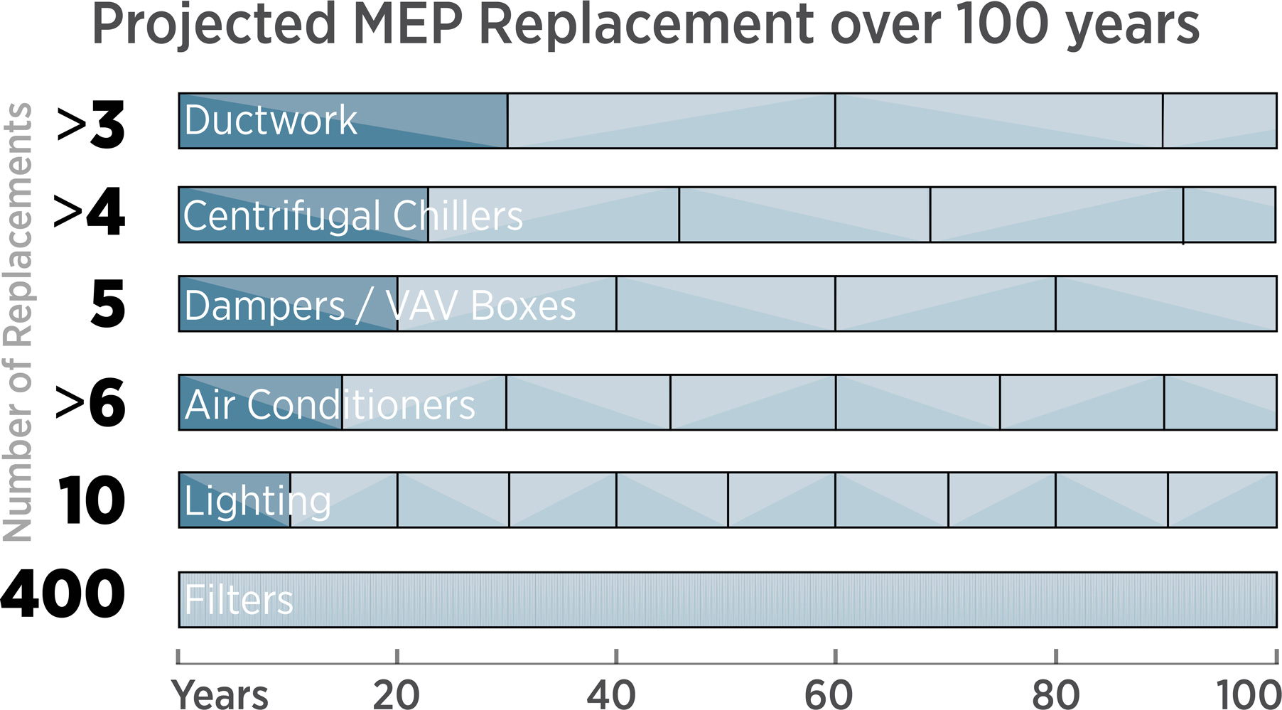
ASHRAE has assessed median replacement cycles for common equipment types, with air filtration media added based on quarterly replacement. Investing in commercial-grade equipment with higher longevity can be a long-term carbon reduction strategy
What Do Refrigerants Do?
Most mechanical systems – and nearly all cooling systems – also contain refrigerants (a good primer here). While small by volume, most refrigerants have a GWP (Global Warming Potential) hundreds or thousands of times greater than carbon dioxide, with significant global impact. One common refrigerant, HFC (hydrofluorocarbon) R-410a, is 2,088 times more potent than CO2 over 100 years; leaking 3-4 lbs of R-410a, the amount found in a residential heat pump, provides warming equivalent to driving a gas car for a year. HFC refrigerants are being phased out in some places, making way for low-GWP refrigerants, including CO2 (with a GWP of 1) for some applications. Post 05 discusses the impact of some common refrigerants and their CO2 equivalent.
What do refrigerants do? The refrigeration cycle for air conditioning (cooling) compresses a refrigerant until it condenses into a hot liquid, then releases excess heat outdoors (even in 115 degree heat). The refrigerant is then brought indoors, allowed to expand into a gas where it absorbs heat. It is then compressed outdoors to release the heat and the cycle continues, like a sponge moving water by absorbing and then compressing. To provide heating, the process is reversed, with heat being brought indoors. Heat pumps work this way; cold climate heat pumps provide heating even at outdoor temperatures of minus 15⁰F or lower (with electric resistance used below their temperature limit). Each refrigerant is designed to have the ideal temperature for boiling and condensing for use in a mechanical system.
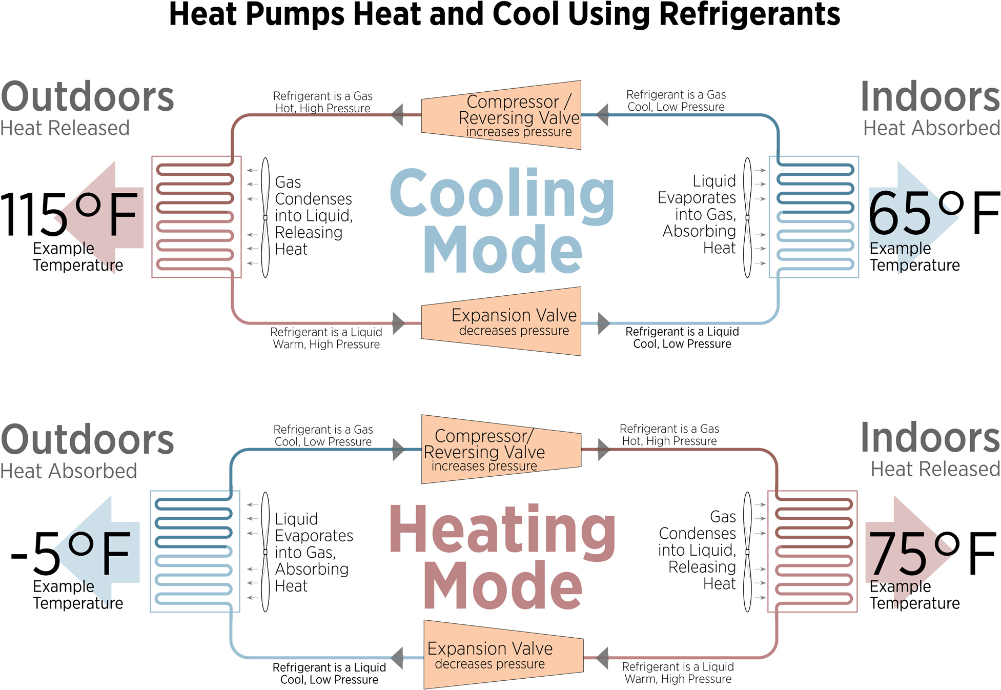
Refrigerators, air conditioning systems, and all heat pumps use the ‘Refrigeration Cycle.’ The cycle compresses and expands refrigerants around their boiling point to efficiently move heat from one place to another using the energy storage capabilities of state change. A reversing valve allows a heat pump to provide both heating and cooling.
Why not use low-GWP refrigerants now? Refrigerants (and equipment designed to use them) are created to balance cost, safety, GWP, regulations, and the overall efficiency of the heat transfer. As electricity sources near zero carbon, leakage of high-GWP refrigerants can be more impactful than the energy use emissions advantage of heat pumps, spurring a need for scaling of low-GWP refrigerants.
Refrigerants are primarily released into the atmosphere during construction (when systems may not be sealed), operations, and equipment demolition (when they are sometimes vented). During demolition, all refrigerants should be recaptured: some can be reused, others should be destroyed to avoid their high global warming potential. While many jurisdictions ban refrigerant venting, these laws are often unenforced in the US. Refrigerants also leak during standard use, especially from systems with many field-fabricated joints such as in Variable Refrigerant Flow (VRF) systems and supermarket systems. Minimizing and simplifying refrigerant runs helps reduce leakage rates, including reducing piping lengths and the number of fittings.
Refrigerant emissions are considered Scope 1 emissions since they are directly controlled by a building owner. They are also considered embodied carbon since they are initially put in a building (A1-A5), replaced over time (B modules, which are operational emissions), and decommissioned at the end of life (C and D modules).
Assumed leakage rates are included in the ASHRAE 228 table below and vary widely among different sources. Actual leakage rates have been studied but vary widely between buildings. Facilities engineers know how much additional refrigerant they regularly add to keep a system running.
The MEP 2040 Commitment has released a Refrigerant Impact Calculator tool based off several datasets and timeline assumptions. LEED has included refrigerant management for several cycles, using a prescriptive approach or a calculation.
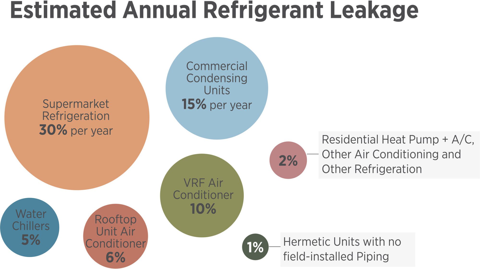
ASHRAE 228 projects estimated refrigerant leakage rates for various systems. CIBSE, BREAM, EPA and the GHG protocol also have factors that vary.
The Future of Refrigerants: Leading the Charge
The electrification of heating (using renewable energy) will reduce total emissions but will also radically increase the use of refrigerants. Reducing the impact of refrigerants is one of the top ten global climate solutions according to Project Drawdown, with alternative refrigerants suggested as a 40-Gigaton potential reduction between 2020 and 2050. Political action includes the 2016 Kigali Amendment, adopted by the US and 146 other countries, as well as some states and municipalities; the US Environmental Protection Agency (EPA) has an 85% phasedown schedule over the next 12 years and is estimated to reduce up to 0.5C of warming by 2100. With refrigerants part of Scope 1 emissions, some large corporations, including Microsoft, have voluntarily agreed to the Kigali Amendment as well.
The lower carbon transition sometimes steps from ASHRAE safety classifications A1 (no flame propagation) to A2L (low flammability) or natural refrigerants (which have varying flammability and toxicity characteristics). Since A2Ls are slightly more flammable, codes and standards are being updated to safely support their use. Natural refrigerants include CO2 (GWP of 1), propane (GWP of 4) and ammonia (GWP of 0).
Most equipment and piping is chosen to work with a specific refrigerant; replacing the refrigerant type to lower the GWP is not always possible without renovation, potentially including piping replacement, since refrigerants operate at different pressures and efficiencies. Building owners should be aware of the shifting regulatory landscape of refrigerants as they select new equipment and systems; some higher-GWP refrigerants may not be available (or at the same cost) when a future recharge cycle is needed. To mitigate risk, a system can be designed to use very low GWP refrigerants, keep refrigerant runs short, or simply use hydronic (water) systems to handle heat transfer instead of refrigerants.
Next generation refrigerants are already beginning to appear on the market, including low and zero GWP options. The ideal is for low-GWP drop-in (or direct replacement) refrigerants to be developed so they can be used within existing systems without major modification.
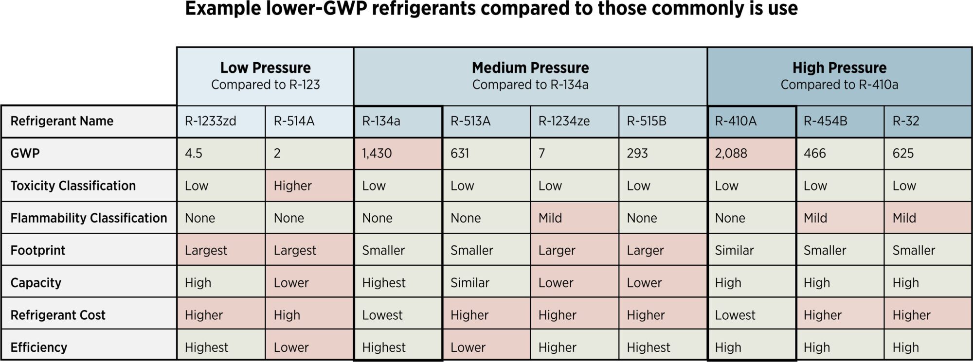
Lower GWP refrigerants exist today and many more will be developed over the next decades. This chart compares some information of lower-GWP options to commonly used refrigerants today. Information from Johnson Controls.
M+P Primary Equipment and Data
If two mechanical systems are equally all-electric and energy efficient, very little advice is available to choose between them, except: 1) some mechanical systems – notably Variable Refrigerant Flow (VRF) systems – contain more refrigerants and site-built VRF refrigerant piping can leak significantly more than that contained within a sealed piece of equipment; and 2) systems that weigh less are likely to have a lower embodied carbon since most MEP systems are primarily made of metals with high embodied carbon density. Filtration media, sometimes replaced quarterly, can also sum to a significant source of emissions.
M+P systems cannot easily be compared because of a lack of EPDs for MEP equipment and components, creating a blind spot in our carbon accounting. To fill this data gap, CIBSE TM65 provides a simplified way to estimate the embodied carbon of MEP (example here) components; a North American version is due to be released Fall ‘23. Some initial data based on TM65 includes a cursory estimate of 9kg CO2e emissions per kg of MEP equipment. The MEP 2040 has adopted a timeline for members to ask for TM65 information, and later EPDs, across a wide variety of commonly used equipment. Everyone in the buildings industry can begin asking for data according to this timeline. Per TM65, the simplest way to estimate the embodied carbon of MEP components is to multiply the weight of each system by LCI (Life Cycle Inventory) data, with other factors being applied.
The TM65 method relies on construction data points commonly available: for instance, sheet metal and pipe are often priced by weight. In addition, the weight of Air Handling Units and other major equipment is often known since curbs and pads are provided for them as a normal part of structural design. These allow cursory estimates and comparisons of embodied carbon.
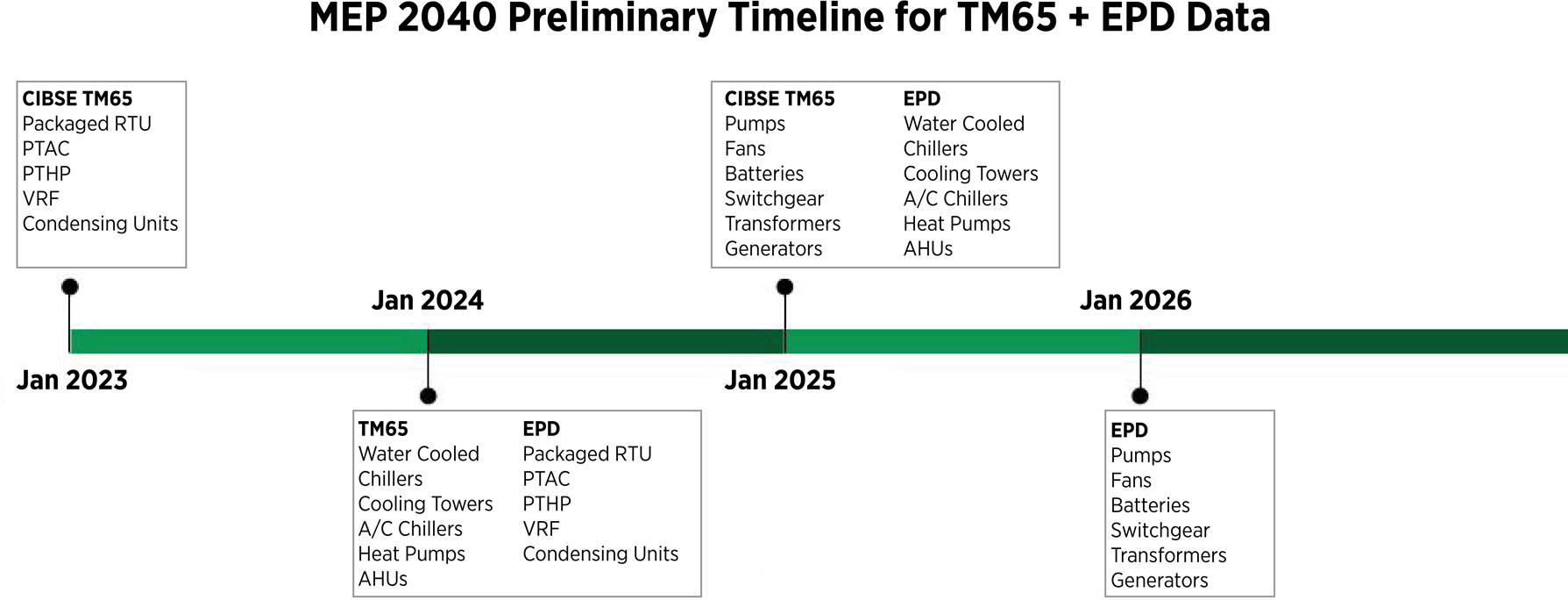
A near-term plan for requesting embodied carbon data on MEP systems, including the use of CIBSE TM65 and EPDs. Image from an MEP 2040 overview presented by Kristy Walson.
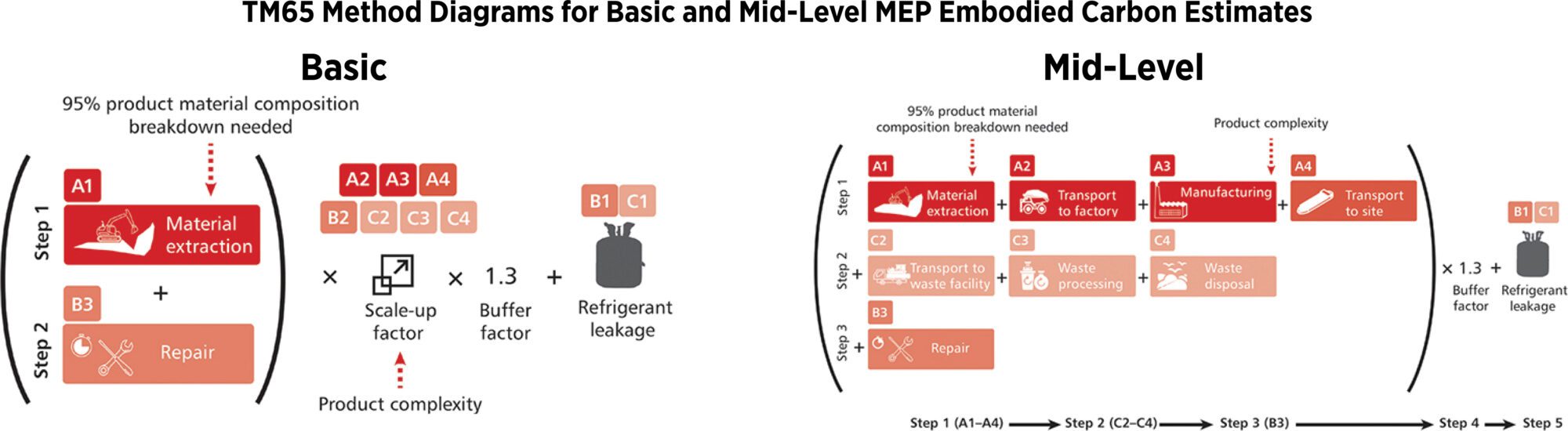
Basic and Mid-Level calculation overview per TM65. Advanced calculations include: BS EN 15804 + A2 Compliant EPD.
Large manufactures such as Trane, Grundfos, and Mitsubishi are beginning to offer TM65 calculations or EPDs for their products, but many times, these MEP systems are custom built at smaller manufacturers; the complexity of this machinery also adds to the difficulty as they are made up of multiple materials, many that result in high GHG emissions during their creation. And due to this complexity, there’s no standard system currently established for reporting, making comparison difficult.
Large equipment also has structural requirements that are impactful, and many pieces of equipment also demand large penthouses or other rooms. The embodied carbon, including structure, of these enclosures can be significant, even if they are not directly counted in the MEP embodied carbon bucket. Eliminating penthouses and equipment rooms, or reducing their size due to reduced loads and efficiency, can be a cost and carbon win if equipment longevity is maintained.
MEP distribution
Distribution systems and terminals (including lighting) may be another overlooked source of emissions. They are frequently demolished and rebuilt as part of renovations, often well before their functional life is over. Because of this they have an outsized cumulative effect on total carbon and may be grossly undercounted when frequent renovations are expected. As described in Post 09, designing for disassembly, reuse, and retaining materials in place are the primary carbon reduction strategy of nearly any renovation, including electrical, lighting, plumbing and ductwork.
Exact quantities of MEP distribution are often not known early, but MEP material weights can be estimated and optimized during design since they are often part of subcontractor pricing models.
The chart below illustrates the primacy of ducts and pipes in terms of embodied carbon of MEP systems. One strategy, lowering embodied carbon by using plastics instead of metals in distribution systems, should be balanced against health effects and longevity. Fabric ductwork, often made of polyester, has lower embodied carbon than sheet metal and can have other advantages. In contrast, The Living Future Institute (ILFI) advocates against building with several commonly used plastics which might appear to reduce embodied carbon. PVC (Polyvinyl Chloride), for example, is lightweight, cheap, and has a lower carbon intensity compared to metals. Known carcinogens, however, are part of PVC (its ingredients, manufacturing, and end-of-life) so PVC should be avoided wherever possible. Vinyl production also drives primary demand for asbestos imports to the US which have a long history of equity and human health impacts. (LMN has a policy against using Vinyl or PVC.)
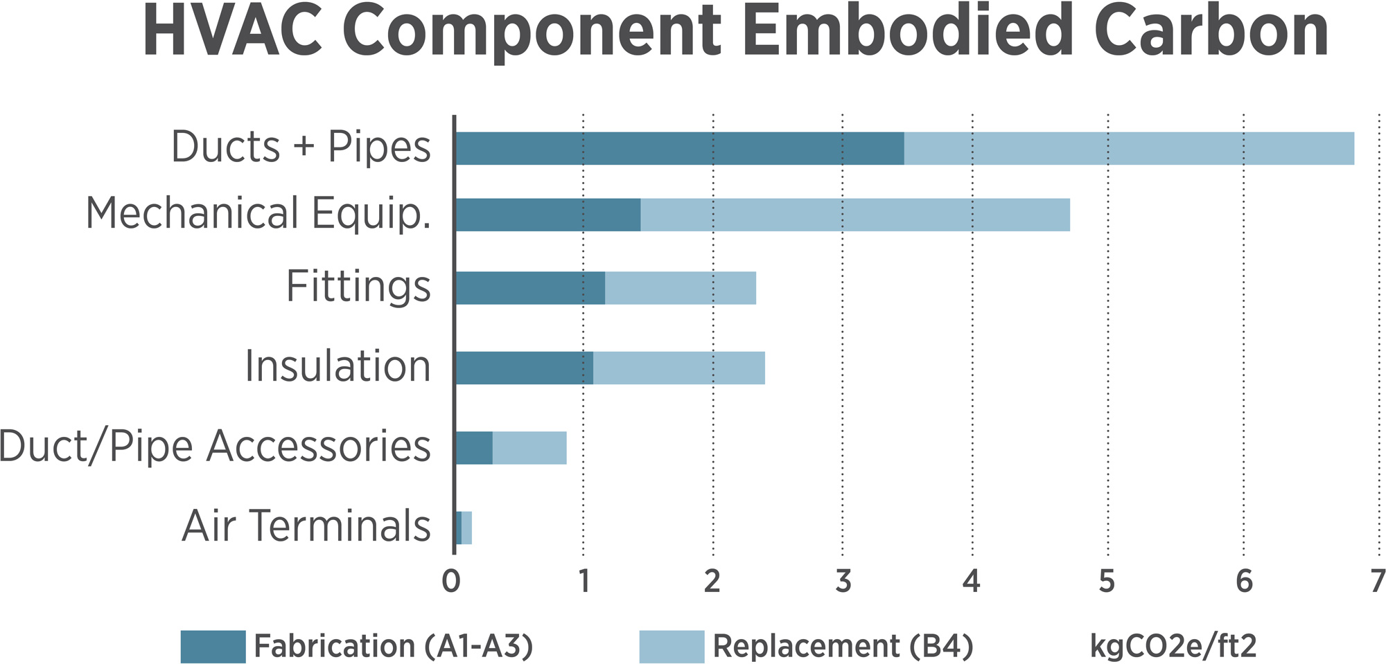
According to one detailed HVAC study, distribution systems account for a majority of the embodied carbon of an HVAC system. Note that replacement of equipment should be lower than shown if the MEP 2040 is successful in procuring lower-GWP equipment. Note that air filters that are changed frequently (not included here) can also be a significant source of embodied carbon.
Lighting, Renewable Energy and Electrical Systems
Understanding the cycle of interior renovations – every 5 years in some markets – is necessary to project the long term embodied carbon of lighting and electrical components since they are often demolished before their functional life is over. Post 09 covers the circular economy, while Post 15 covers interior renovations and lighting in more detail.
Beyond lighting, other common equipment is also often excluded from LCA calculations. Elevators, escalators, and other building systems are complex, packaged goods that are made from metal and other high GWP materials, often customized to suit the needs of each building; this means developing EPDs may not be practical.
We do have some EPD data for photovoltaics (PV) panels, increasingly installed on buildings. In Post 06 we suggest that a total carbon accounting needs to include the embodied carbon of all renewable energy to power a building whether it is on or off-site, and showed estimates that it accounts for around 15-45 kg CO2e/MWh. We also showed estimates that other, off-site energy sources generally have higher embodied carbon than PV. (We are undecided on whether renewable energy to power EV charging on site should be included in a total carbon accounting). This method likely undercounts the actual, demanded embodied carbon of adding electricity generation to support a new building since storage is required for intermittent resources like solar, but provides a reasonable enough estimate for now. The end of life for PV panels is evolving, with materials recovery and recycling efforts ramping up as large numbers of panels are aging.
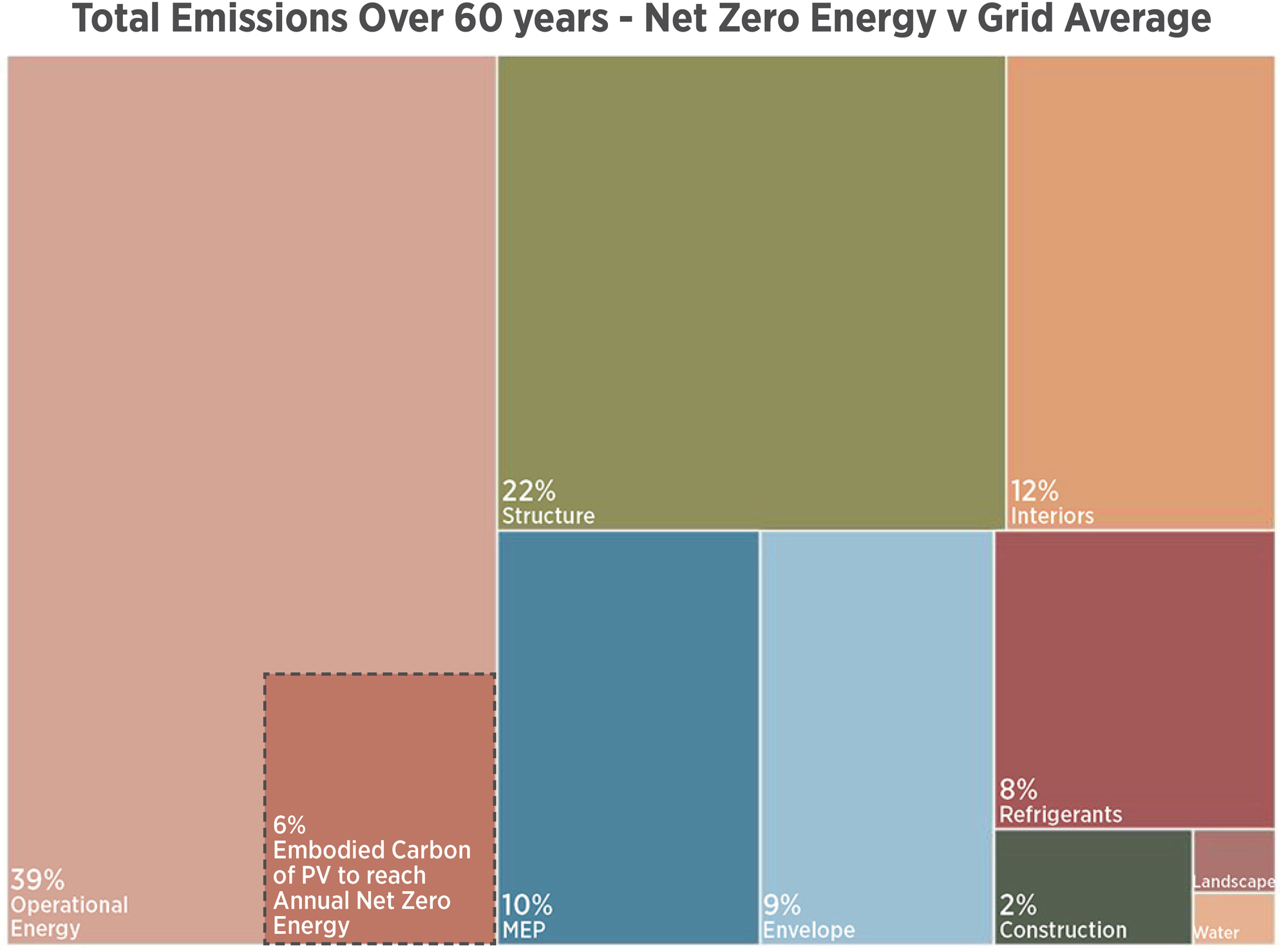
Using the same project example from prior posts, operational energy use carbon is compared against the embodied carbon of PV panels to reach annual net zero energy. This assumes no on-site electricity storage, PV embodied carbon of 600kgCO2e/kW and an initial 400 kg/MWh grid transitioning to a 70% carbon intensity reduction by 2050. PV embodied carbon has dropped sharply over the last decade as many factories now use solar energy.
Electrical Vehicle (EV) charging at buildings, starting to be included in building codes, can significantly increase the size of electrical service, transformers, and distribution. With charging and demand management, sometimes creative approaches can be grid-supportive and avoid significant upsizing. The embodied carbon of upsizing a transformer to provide EV charging is clearly transportation-related embodied carbon, but it may be difficult to separate out from building-specific embodied carbon. As vehicle, batteries, and standards evolve and harmonize, it’s likely that EV chargers will change frequently sending non-modularized chargers to material recovery centers or landfills. See also Post 13’s discussion on the interaction of EVs, buildings, and the electricity grid.
Since nearly all small modern electronics (phones, computers, lighting) and run on DC (direct current) power and PV generates DC power, some have suggested that we convert offices to use DC wiring to avoid current transformers in every device. While this is possible, DC power often requires larger wiring, so the embodied carbon of the system would need to be considered.
Other equipment
Elevators, escalators, servers, building control systems, data systems, computers, specialized equipment (such as for health care) and other energy using equipment also have a significant embodied carbon footprint. We have even less data on these than we have on MEP equipment, and no widespread initiatives to collect it. For now, it is ignored in nearly all carbon calculations, but would be necessary to address to consider a project carbon neutral.
Conclusions
Selecting MEP systems for energy efficiency and electrification are the keys to low-carbon transition, along with selecting low-GWP refrigerants. While the embodied carbon of MEP systems can be elusive, comprehensive carbon analysis comparing energy use carbon against the embodied carbon of envelope and MEP systems is just becoming possible by using TM65 analysis. There are a few reliable sources to help guide project teams on establishing the embodied carbon of refrigerants via leakage, and there are always alternatives to refrigerant-dense systems. While refrigerants are of concern, electrification is nearly always the low-carbon solution over the long term. Right-sizing equipment and operational energy reductions via envelope performance (don’t forget to consider occupant behavior during design) are excellent strategies to avoid MEP embodied carbon.
Join the MEP 2040 in the push for transparency, asking for TM65 and EPD data on equipment over the next few years, which will eventually make comprehensive carbon analysis widely possible. Until this data is available, equipment and component weight is a decent proxy for carbon emissions: systems that weigh more are likely to be responsible for more embodied carbon.
Once a system is selected, right-sizing it for today and near-future climate conditions reduces MEP embodied carbon and cost. To this end, investigations should be part of all projects to determine if envelope improvements can eliminate or significantly downsize an MEP system (Post 12).
It is LMN’s opinion that the embodied carbon of renewable energy that supports a building’s operation should be included in any net zero carbon claim, as along with the embodied carbon of MEP systems and estimated refrigerant use and leakage.
Thanks to our external collaborators and peer reviewers
Kim Shinn (TLC Engineering), Kayleigh Houde (Buro Happold), David Mead (PAE), Rachel Wrublik (PAE), Danielle De Castro (PAE), Louise Hamot (Introba), Lyle Keck, (Affiliated Engineers, Inc), Katherine Anderson (Affiliated Engineers, Inc), Brett McQuillen (Affiliated Engineers, Inc), Matthew Veloz (FSI Engineers).
LMN Architects Team
Huma Timurbanga, Justin Schwartzhoff, Jenn Chen, Chris Savage, Kjell Anderson
Posted: 08/25/2023
The text, images and graphics published here should be credited to LMN Architects unless stated otherwise. Permission to distribute, remix, adapt, and build upon the material in any medium or format for noncommercial purposes is granted as long as attribution is given to LMN Architects.