#pathtozerocarbon, #sustainability
12 – Envelopes – What Does High Performance Mean?
When we think of a building, we usually picture the outside: classical columns, brutalist façades, or contemporary compositions of windows and opaque areas. Prior to modern heating, cooling and electric lighting, architects designed façades to ensure adequate daylight and thermal comfort though massing, window layout, and design of heating sources that included proper solar orientation. We quickly forgot these lessons as energy for heating, cooling, and electric lighting seemed limitless and without downsides; we relied on engineers to make highly glazed sealed boxes habitable.
We now know better, rediscovering that controlling heat gain and loss through windows and facades are a critical part of architectural design intent. Façade design also now includes a conscious embodied carbon investment in materials and has an influence on the size, cost and embodied carbon of mechanical systems and energy generation systems as well. As we invest more embodied carbon in facades to improve comfort, resilience, and energy performance, how do we assess whether we are making a carbon smart choice?
Understanding Façade Materials’ Embodied Carbon
The free Kaleidoscope Tool compares several opaque façade types, including options to look only at upfront embodied carbon or to include a 60-year timeframe (this includes less durable cladding materials that require periodic replacement). These emissions match LMN’s Whose Wall Wins study, showing roughly 5 to 25 kgCO2e/sf of new façade area, and this façade embodied carbon is around 5-15% of total embodied carbon (with many assumptions and caveats).
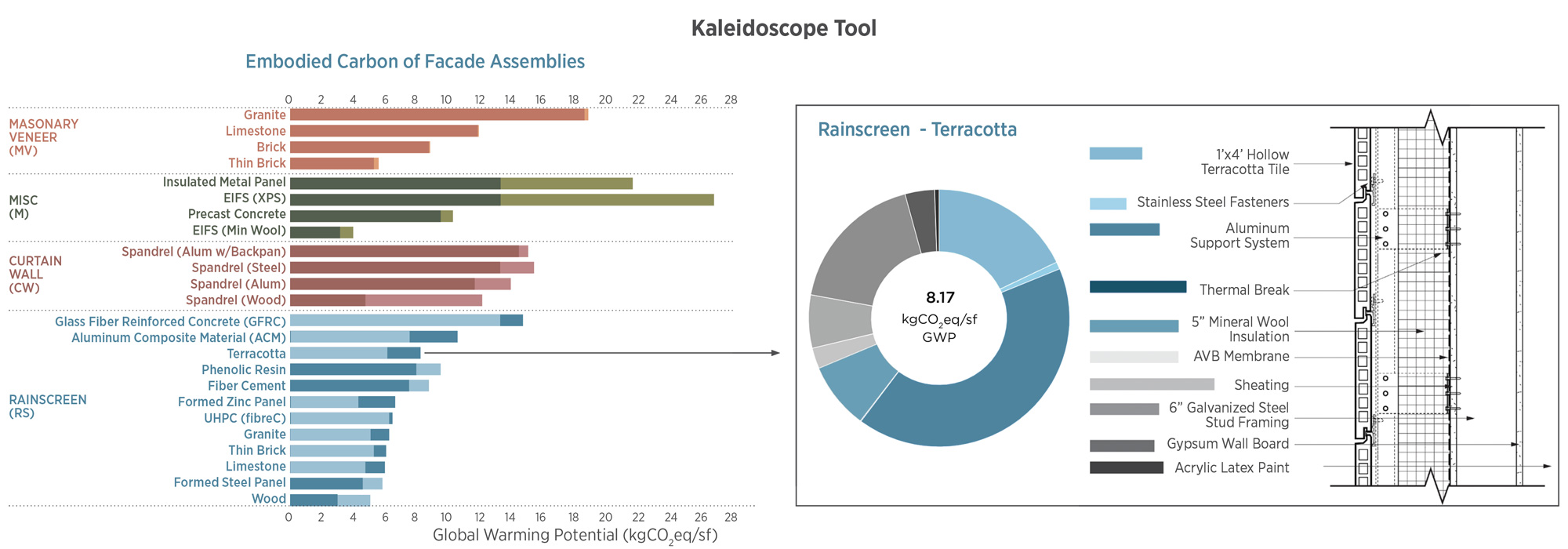
The free, online Kaleidoscope Tool compares common façade assemblies for embodied carbon across a 60-year lifespan. Assemblies contain the same U value, but for some of them the service life is expected to be less than 60 years, so replacement is expected within the study duration, increasing embodied carbon.
Some examples exist of carbon sequestering facades.
Opaque facades usually include a structural material (often studs), insulation, sheathing and waterproofing, and a cladding material, along with windows and doors. Heavier façade materials require additional structure at the floor level or within the stud area that should be included when comparing systems. We have embodied carbon EPD data on many of these products.
Two opaque materials stand out: insulation and heavy cladding materials. Insulation embodied carbon can vary significantly from XPS (averaging around 2 kgCO2e/sf/unit R, although some state’s laws significantly lower this) to mineral wool (0.5 kgCO2e/sf/unit R) to carbon-sequestering biogenic materials like cellulose, cork, or mushroom board. Many buildings are also designed to be fossil fuel free despite using fossil fuel-based insulations. Unlike many other materials that see the majority of their impacts in stages A1-A3, insulation has significant impacts across product lifespans. Blowing agents used in foamed insulation are responsible for much of the embodied carbon and are released as the product off-gas during its life span. For this reason, CLF Baselines, which typically consider only A1-A3, include modules A1-A5, B1, C2, and C4 for insulation materials. Advanced blowing agents developed in the last decade significantly reduce embodied carbon, and increasing blowing agent regulation is standardizing lower-GWP insulations.
Heavy cladding materials like precast concrete, brick, and stone often have higher upfront embodied carbon due to their components as well as requiring additional structure for support. However, with good design and maintenance these materials can last for over a hundred years; however, impacts and risk of being torn down early should be considered if products cannot be disassembled and continue as part of the circular economy.
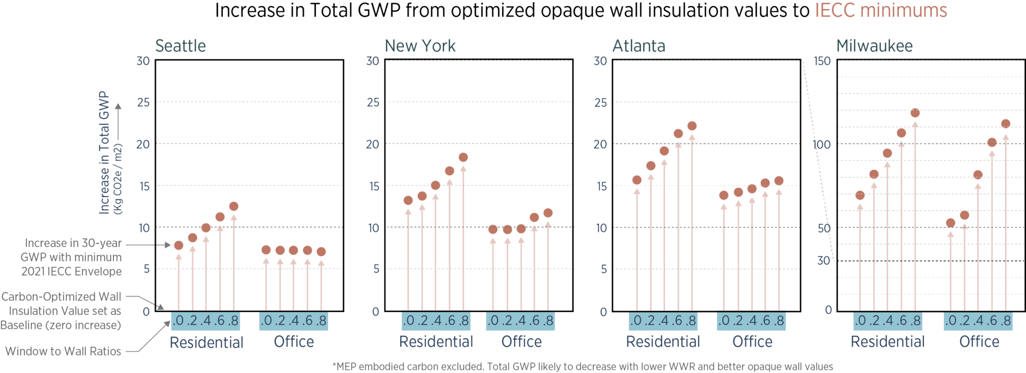
A study comparing the 30-year operational and embodied carbon emissions of optimal opaque wall assemblies and opaque wall assemblies representing 2021 IECC minimum requirements. The study assumes 3% reduction in operational carbon annually due to grid greening. Analysis shows that underinvestment in envelope embodied carbon by the 2021 IECC prescriptive requirements results in higher total carbon due to increased operational energy use in the scenarios above. Credit: University of Washington Integrated Design Lab
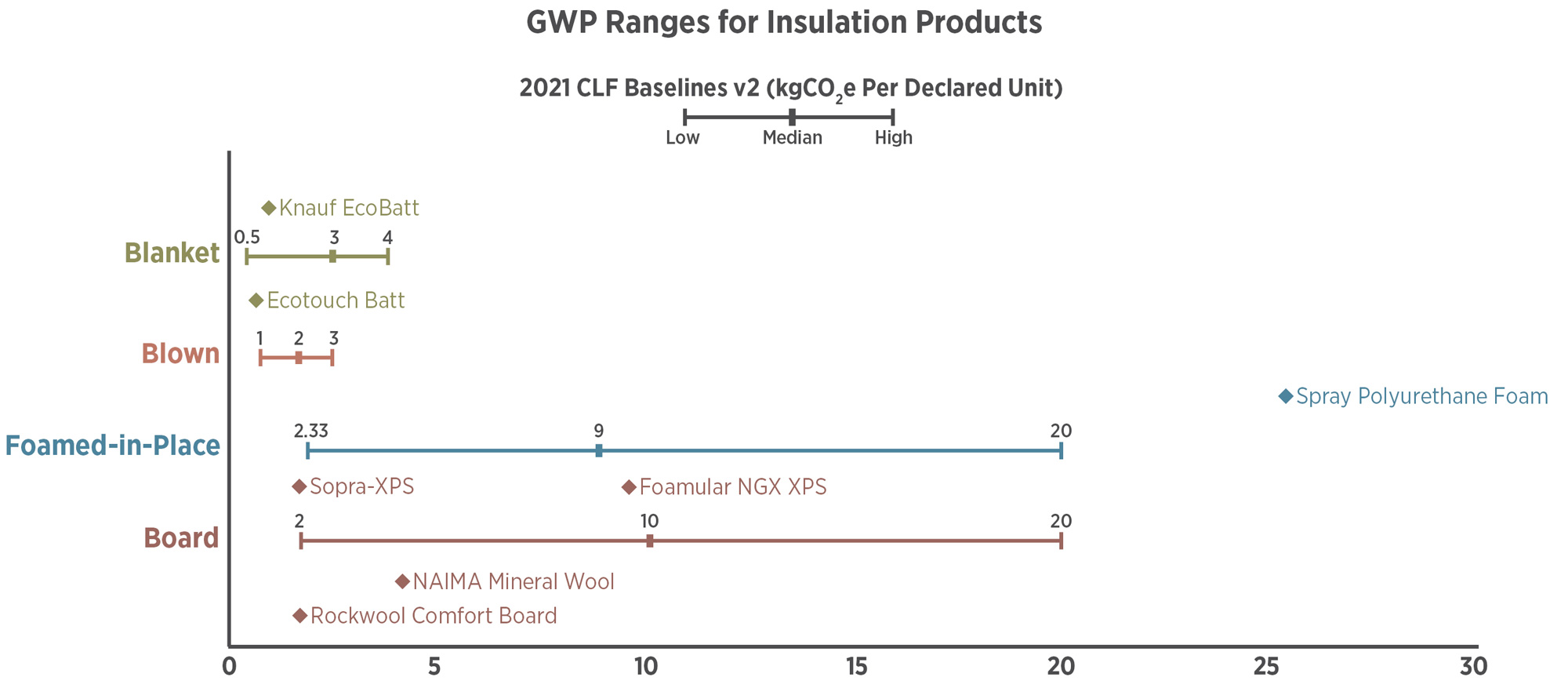
Insulation materials vary widely in performance and embodied carbon. The 2021 Carbon Leadership Forum High, Typical, and Low baselines are shown above, along with several EPD values. While board insulation has historically been high carbon emissions, modern blowing agents are making these competitive with other insulation types. Information above from: NAIMA Mineral Wool National EPD, Soprema Sopra-XPS, and other EPDs
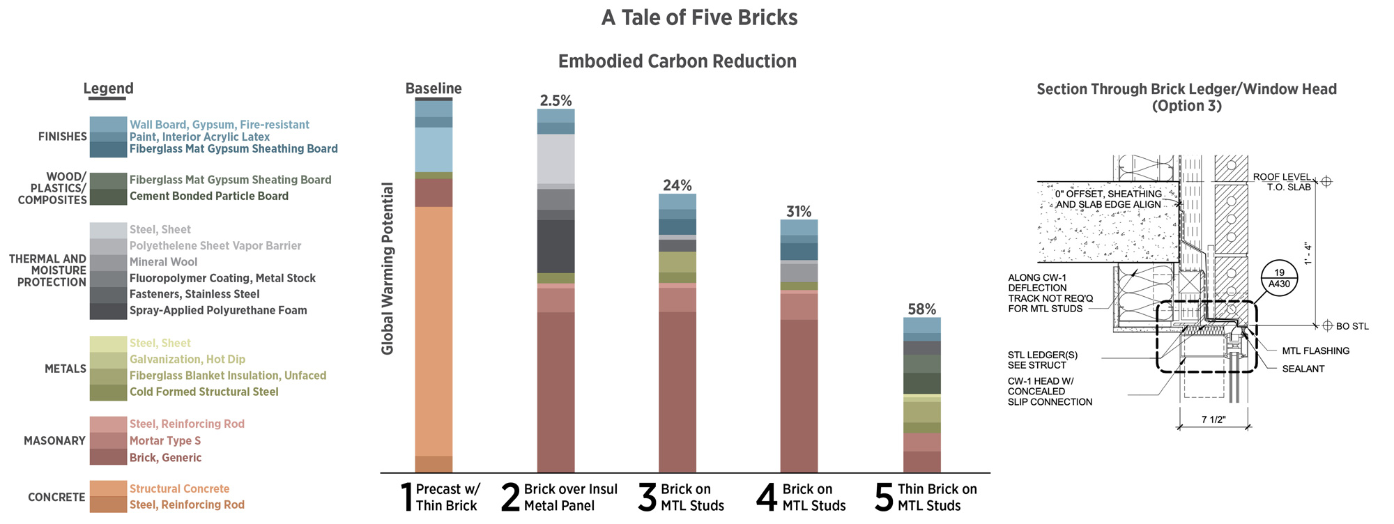
Optimization can happen even after a cladding system has been chosen. These are 5 brick walls that we have detailed and investigated use of on our projects. Note that reducing thermal bridging by using a knife plate instead of a continuous ledger reduces both heat loss through thermal bridging as well as embodied carbon due to less steel used.
Openings: Not many EPDs exist for windows or glazing systems, but for A1-A3 Arcadia’s Curtain Wall shows around 24 kgCO2e/ft2, Kawneer’s Storefront shows around 14 kg CO2e/sf, Inline’s fiberglass window is around 7 kgCO2e/sf, and a study of European fenestration provides a range of 15-48 kgCO2e/sf for commercial systems. Commercial buildings are increasingly built with premanufactured window systems, often with integrated spandrel panels. To make up for poor thermal performance, spandrel curtain wall often includes an insulated back-pan with an additional, stick-built insulated wall behind it – this often has a higher embodied carbon than opaque wall, along with poorer overall performance due to thermal bridging. Wood and fiberglass window frames have relatively low embodied carbon.
Existing façade work can take a more surgical approach – see Post 10 for COTE Top Ten winners that reused existing buildings. In general, cost-effective envelope energy upgrades (two examples) are likely to pencil only when capital is already allocated for improvement or replacement of some envelope systems, or during major renovations or repurposing. Well-designed opaque facades should last for hundreds of years, but modern double or triple glazed openings last only as long as the seals and the desiccant strips within them, perhaps 25-40 years, meaning replacement cycles occur more frequently. When glazing replacement occurs, advanced glazing, airtightness, and additional insulation can pay back. From a circular economy perspective, most modern windows use laminated glass or low-e coatings that make them difficult to recycle, but aluminum is a great circular economy material; from our perspective including the end-of-life recycling scenario in aluminum is reasonable.
How Do Facades Improve Building Performance?
Facades mediate between outdoor conditions and desired indoor comfort conditions: temperature, humidity, water, wind, solar energy, light, views, and more. While mechanical systems provide the actual heating and cooling, their size, cost, and energy use is a result of massing and façade design.
Comfort. Our experience of thermal comfort is deeply impacted by facades, especially near them. Windows and uninsulated walls are often cold to the touch in winter and warm in summer; since thermal comfort is more impacted by nearby surface temperatures than air temperature (can be called asymmetrical discomfort) this means otherwise pleasant air temperatures are uncomfortable when we are near cold or warm surfaces such as under-insulated or overglazed facades.
To avoid perimeter discomfort in cold climates, many engineers suggest a second heating system at the perimeter that requires space and increases cost and embodied carbon; in many cases a better envelope may provide equal comfort and cost less. You can see some results by adjusting the operative temperature within the Berkeley Comfort Tool. The Glazing and Winter Comfort Tool explores being near a cold window in more detail.
Resilience can mean many things, from social resilience in the face of threats to continued physical operations like water treatment after disasters. Within the buildings sector, high performance facades add resilience: during heatwaves or cold snaps, mechanical systems don’t provide enough heating or cooling, but a great envelope can maintain more consistent temperatures, called passive survivability. The TEDI metric used in Canada, considers this. Since more people die in heatwaves than in any other type of disaster, proper orientation, correct glazing, and operable windows can be part of a critical life-saving resilience strategy.
Loads. During normal operation, the required heating and cooling to maintain comfort are commonly called ‘loads,’ and there are two primary kinds of loads influenced by the envelope design:
Annual Heating and Cooling Loads: The amount of hour-by-hour heating or cooling required by a building to maintain comfort over the course of a year. Heating and cooling loads are a sizeable part of the total annual Energy Use Intensity (EUI, measured in kBtu/sf/year in the US), a common measure of building performance.
- A ‘free run’ energy model looks at the heating and cooling loads imposed by the façade regardless of mechanical systems. The TEDI metric uses this method to set the minimum envelope performance.
- Heating Loads are estimated by calculating the thermal conductance (UA value) of an envelope. The U value describes the amount of heat that flows through a material or assembly, and A refers to the area of the material. By multiplying all areas of façade by its U value and summing them, you can quickly compare design options for the envelope contribution to heating load. Thermal bridging must be part of any U value consideration for all assemblies. Note also that the ‘center of glass’ U value is given for most windows; The ‘assembly U value,’ including thermal bridging through the frame, is the only realistic way to assess window thermal performance.
Peak Heating and Cooling Loads: the amount of heating or cooling required at the most demanding hour of the year. A cold winter morning with no solar gain, lights, equipment or people to provide heating usually determines the peak heating load; a hot, sunny afternoon with full occupancy, lighting, and equipment often determines the peak cooling load. Mechanical systems are designed to handle peak loads, so increasing peak loads generally increases the size and cost of the system. Peak loads often correspond to the most carbon-intensive and highest priced electricity as well (Post 06). Solar loads through windows are often the biggest design driver of peak cooling loads, so reducing these through window to wall ratio, low SHGC, and exterior shading has a significant impact on total carbon, well beyond just the energy savings from these measures. Light-colored roofs and low-SHGC windows in sunny areas are often a no-cost peak cooling load reduction.
Note that peak heating and cooling loads can be calculated and used at a building scale to understand equipment sizing, as well as at a room scale to determine air supply temperature and other aspects of mechanical design. Sometimes the peak cooling in one space determines the air supply temperature for a large portion of a building.
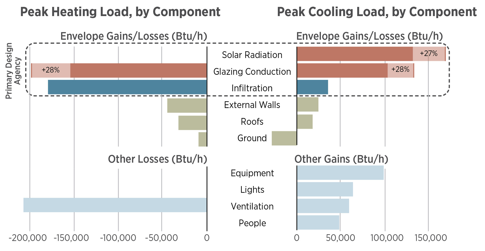
Peak heating and cooling loads for a modeled 3-story office building in Chicago with 37% glazing. Note that glazing properties are the two largest contributors to peak cooling load, while infiltration (air leakage through the façade) and glazing conduction are the two of the top three contributors to peak heating load. Design teams have primary agency over these important factors. Increasing window to wall ratio from 37% to 48% increasing window-related loads as shown. The model used ideal loads within cove.tool, meaning the results are independent of heating and cooling system selection; this analysis type is suitable for architects to use to understanding envelope performance.
Passive House v. The World
The Passive House US standard and the original, used on tens of thousands of residential and commercial buildings (including high rises) worldwide, are a one-stop shop for an envelope-first system that leads to low-operational carbon buildings with drastically reduced peak loads and smaller mechanical systems. With a focus on envelope, including fenestration orientation, airtightness, and thermal bridging (plus energy recovery from exhaust airflow), each advancement of the energy codes gets closer to Passive House standards.
Commercial energy modeling practice differs from passive house modeling practice, and often fails to properly inform architects about energy improvements that envelope improvements provide. This is a complicated, but in general passive house modeling and prescriptive requirements specifically include thermal bridge modeling, including at the intersections of various assemblies, and envelope airtightness requirements, while commercial energy modeling practice and codes typically do not allow improved airtightness and sometimes ignore thermal bridging. In addition, passive house includes maximums for peak heating and cooling loads as well as annual energy use.
Building to passive house standards results in a comfortable space that is nearly thermally uniform, even with minimal heating or cooling in extreme climates. Many modern non-passive house buildings are simply not comfortable no matter how much heating or cooling are applied because of poor envelope design and a lack of comfort uniformity. Since we are stuck for decades with thermal comfort problems stemming from façade design, we often simply increase the heat in winter and increase the cooling in summer beyond what would otherwise be necessary. This wasted energy could be modeled using dynamically adjusted set points based on asymmetrical discomfort, but often is not.
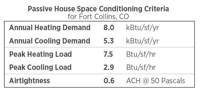
Passive house has requirements for peak heating and cooling loads, annual heating and cooling demand, airtightness, and more. These specific requirements are for a medium sized home in Fort Collins, Colorado.
Passive house can lead to over-insulating a building in some cases, especially one that generates a significant amount of heat internally via people or equipment. And since passive house buildings use more insulation material, the choice of low-GWP insulation is paramount.
Cost Neutral Energy Savings?
Referred to as tunneling through the cost barrier, many design teams believe that if the process of design, energy modeling, and cost modeling works smoothly, additional envelope investments can lead to decreases in other system costs, providing cost-neutral energy savings that increase comfort, resilience, and carbon emissions.
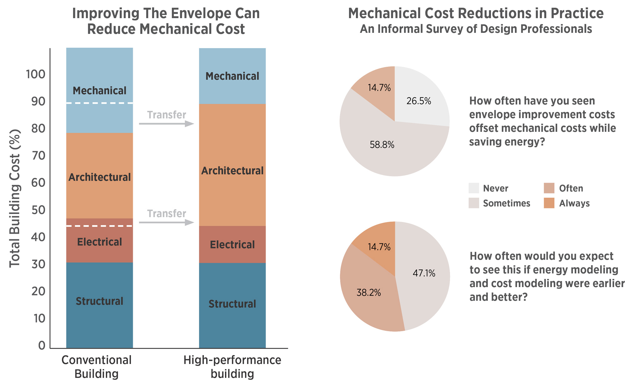
High performance design often shifts dollars and carbon from mechanical systems to envelopes. Better envelopes reduce the size, cost, and embodied carbon of mechanical systems.
Teams are more likely to find these cost-neutral energy savings in higher-numbered climate zones (perhaps 4 and above), buildings with a high ratio of envelope to internal area, in sunny climates and highly glazed buildings, and when starting with envelopes with lower performance than the latest energy codes (IECC 2021 or ASHRAE 90.1-2022).
Inaccurate cost and energy modeling can be a hindrance. Often when architects ask to understand the impact of better façades, the energy modeling results show little impact on annual energy loads, but don’t report mechanical sizing reductions (with potential cost savings) due to peak load reductions. Since many designs include thermal bridges, poorly performing windows, or too much glazing, and typical energy modeling practice doesn’t accurately represent the effects of these on comfort and resulting energy use, design teams often make decisions with misleading information.
In practice, cost modeling is also rarely comprehensive: has the mechanical system been re-optimized and re-costed based on reduced loads? Is there a façade performance threshold at which mechanical sizing drops noticeably? Project teams should ask for mechanical engineers and cost modelers to help find the sweet spot whereby reducing loads by a target amount unlocks the first cost savings.
Facades Influence Peak Loads, Peak Loads Influence Carbon
Reducing peak loads almost always reduces annual loads and improves comfort. In addition to comfort, these are other benefits of peak heating and cooling load reductions that should be considered in any analysis that seeks to evaluate the effectiveness of envelope measures.
- Mechanical Systems Size and Embodied Carbon: Peak loads determine the size of the mechanical system. Since mechanical systems can be 10-40% of a new building’s embodied carbon (Post 14) and refrigerants increase operational carbon, embodied carbon invested well in the envelope can pay off right away. Mechanical system embodied carbon is not well quantified yet, with CIBSE TM 65 providing the best current guidance.
- Mechanical System Type: Some efficient mechanical systems, especially radiant systems like chilled beams, have a maximum cooling load that they can temper. Buildings with advanced mechanical systems need to control peak loads, especially solar loads. Often a mechanical engineer can set design targets for peak solar loads to allow advanced systems to be used to reduce energy use carbon.
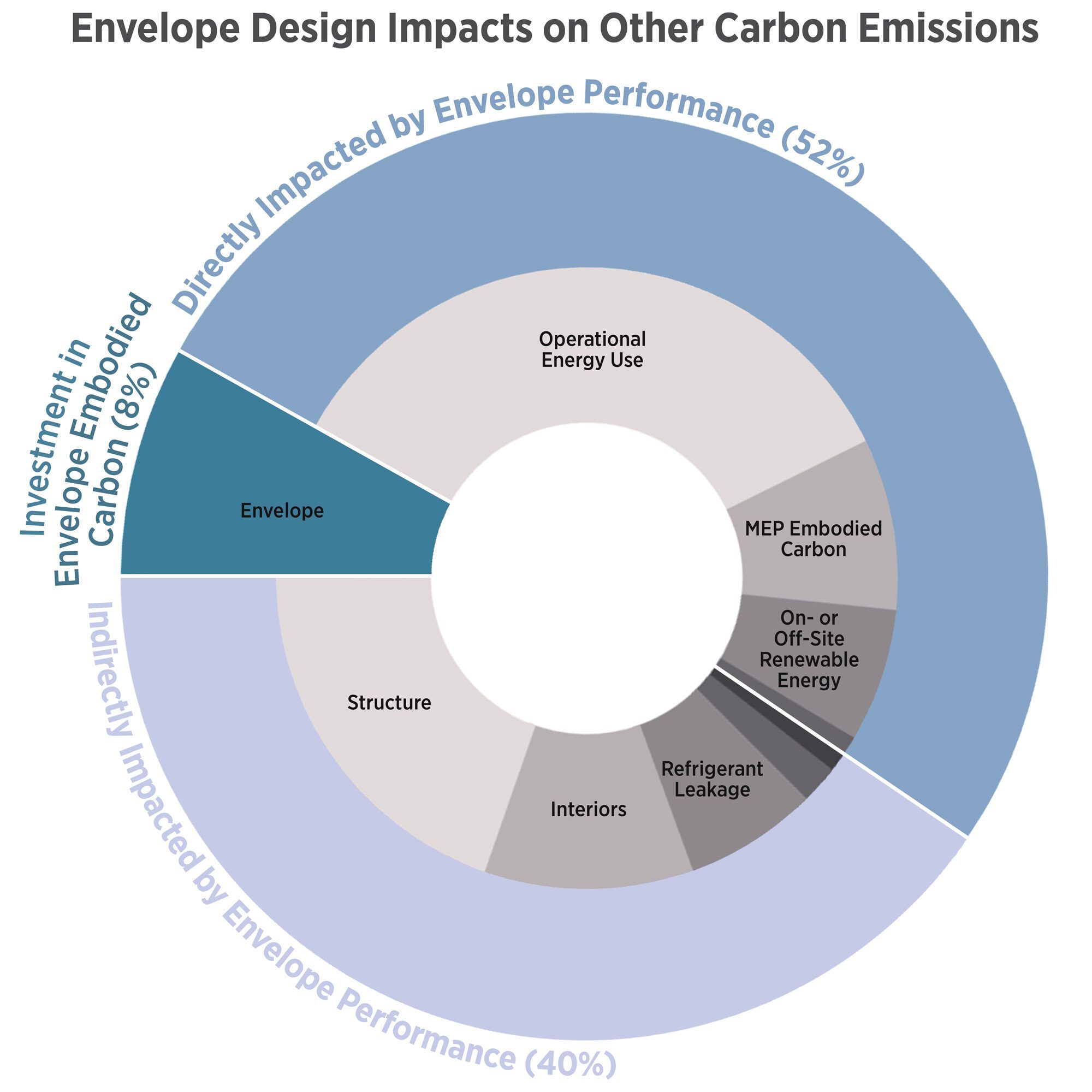
Envelope design directly impacts categories responsible for around 60% of carbon emissions on this example project, showing that increasing envelope carbon to increase performance well beyond current practice is very likely a carbon-smart investment. Envelope design also impacts structural embodied carbon for cladding support, including thermal bridging reductions in some cases.
- Grid Demand: Peak loads themselves contribute to the amount of peak energy that is needed from the electricity grid, described in Post 06. So consequential emissions from lower peak heating and cooling loads include lower embodied carbon and cost of building out the renewable energy grid, including energy storage systems. The primary strategy for a grid-friendly building is a great envelope since other grid-friendly strategies are shorter-lived and are being rapidly improved.
- Energy-related Carbon Emissions: Recall from Post 06 that the season and time energy is used has a large impact on the carbon emissions from that energy: electricity used to cool a building at 5pm is going to have a higher carbon footprint than electricity used at noon in a high-solar grid. This means that shading at 5pm may be a better carbon-reducing strategy than shading at noon.
- Passive Survivability: Facades also play a role in passive survivability during power outages and times of extreme heat and cold.
Designing to Control Peak Loads
Back to the initial question: does investment in façade embodied carbon allow reductions in other embodied carbon and lower operational carbon? In general, the answer is yes, but there are better methods to start: reasonable window to wall ratio, airtightness, and thermal bridging reductions are very low carbon ways to reduce peak loads that don’t require much increased investment and should be pursued first.
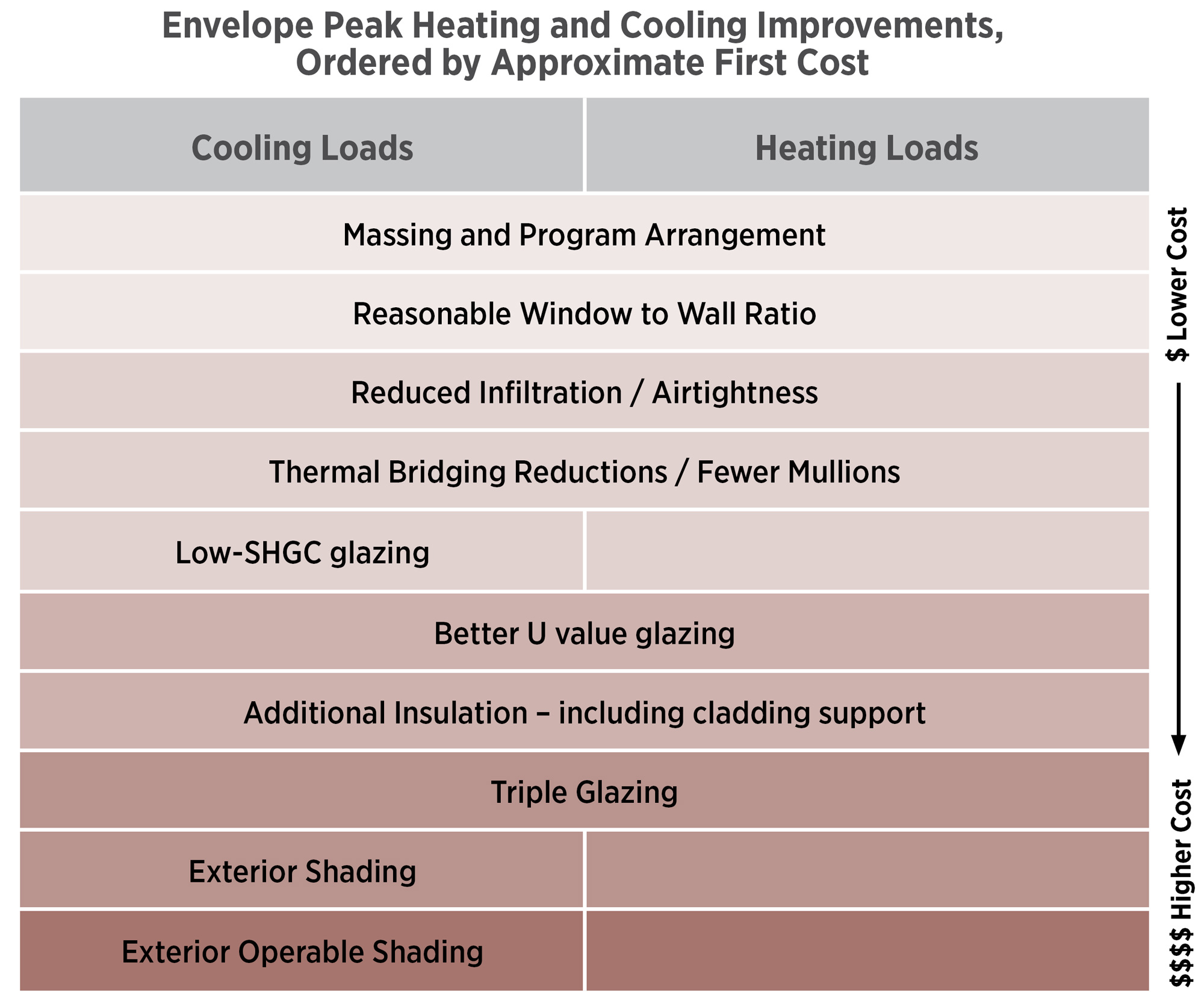
Façade investments can reduce energy use and mechanical cost, especially in extreme climates. The list above is arranged by cost of strategies as well as whether the goal is to reduce cooling loads, heating loads, or both. Ken Yeang’s book is a good resource for massing strategies.
Reasonable Window to Wall (WWR) Ratio. As should be obvious by now, high window to wall ratios (WWR) are not part of a carbon smart building (except when shaded and in very mild climates). High WWR increases solar loads, conduction heat losses, mechanical system size, refrigerant use, water and energy use, and peak electricity demand. While a few net-zero certified buildings have high WWR, a comprehensive consideration of carbon would not come out in favor of this strategy.
Airtightness is based on design, detailing, and diligence in construction. A blower door test should be conducted toward the end of construction, and any deficient areas corrected. This test is increasingly required in residential and commercial energy codes, with Passive House setting the standard for results. Codes and energy analysis practices generally do not allow airtightness improvements to be included in energy modeling, but with a diligent team and outcome-based
Thermal bridging reductions involve reducing heat paths from the interior to the exterior that largely occur through metal and concrete. These are most common in metal penetrations through insulation and in cantilevered balconies. Continuous exterior insulation with advanced cladding supports and using thermally broken window frames are the best strategy. Others include using knife plates for brick ledgers instead of a continuous ledger, using wider stud spacing at insulated exterior walls, and reducing structure in exterior walls that displace insulation. Commercial energy modeling practice usually does not consider thermal bridging, including improvements, in reporting energy use and energy savings. Great design teams will calculate realistic U values for assemblies and thermal bridges and push for this to be part of the energy modeling.
Operable Windows are a special case in façade design. When engineered properly, operable windows can allow natural ventilation to provide cooling and fresh air. For the few climates in the US where natural ventilation can cover peak cooling loads, this can be a cost-competitive strategy; however, climate change and wildfire smoke are making these areas rarer. Most climates the US require additional mechanical cooling, meaning that little or no capital cost is saved via natural ventilation. In this case, operable windows (especially when they are monitored by a building management system, motorized, or require additional HVAC controls) add cost, making them an amenity and resilience investment.
The Math
Important elements to evaluate the carbon impact of facades:
- Embodied Carbon of façade assemblies, plus façade material replacement if necessary. Glazing lasts 25-40 years, but nearly everything else will last at least 60. LMN’s view is that during renovations, opaque areas should be assumed to have full embodied carbon life remaining unless replacement capital is proposed.
- Annual energy-related carbon emissions based on hourly energy use and hourly, forward-looking carbon intensity data (Post 06 and Post 13)
- Ability to downsize mechanical and electrical systems based on envelope-driven peak load reductions, including total refrigerant quantities required. Data on this is emerging now, covered in more detail in Post 14.
- Fractional share of embodied carbon of energy generation systems whether they are part of the project or not: district energy, geothermal, off-site electricity generation, etc. If this is assumed to be PV, embodied carbon may add 10-20% to a building’s total embodied carbon.
Conclusions/Remaining Questions
The way buildings look – facades – determines the total carbon of many other components. By investing money and embodied carbon in facades, designers can reduce peak heating and cooling loads and keep people comfortable passively, which can reduce the total carbon emissions with proper coordination and analysis.
Questions
- When will we have better data on mechanical system types such that we can accurately consider envelope v mechanical embodied carbon tradeoffs?
- What portion of Mechanical system embodied carbon can be reduced by envelope improvements?
- What tools and processes can best support a comprehensive approach to embodied and operational carbon cost and carbon analysis?
Thanks to our external collaborators and peer reviewers
Chris Meek, UW IDL; Kristian Kicinski, Bassetti Architects; Michelle Amt, VMDO; Stephane Hoffman, Morrison Hershfield; Jamie McKay, Morrison Hershfield.
LMN Architects Team
Huma Timurbanga, Justin Schwartzhoff, Jenn Chen, Chris Savage, Kjell Anderson
Posted: 05/02/2023
The text, images and graphics published here should be credited to LMN Architects unless stated otherwise. Permission to distribute, remix, adapt, and build upon the material in any medium or format for noncommercial purposes is granted as long as attribution is given to LMN Architects.